JACOBSIMEONE.NET
Custom PCB for RTD Temperature Measurement
Published: 2025-08-16
Links
At university, my team and I were working on ways to measure ambient air temperature for a weather station that would be deployed outdoors on campus. We had problems in the past using sensors internally in our enclosure, because there was not enough airflow through the inside.
To combat this, we began looking into different technologies used to measure temperature remotely, with most of the circuitry inside of the enclosure, but with a probe on the outside for measuring temperature. This search led to the discovery of RTDs, a type of temperature measurement sensor that changes resistance almost linearly based on temperature.
Design Notes
Note that we later found that a better design for a weather station is instead of focussing on measuring the environment externally, it is better to create an enclosure that encourages airflow and mounting sensors internally. Later designs included ventilation to encourage airflow.
How an RTD Works
An RTD (Resistive Temperature Detector) is a device that allows a user to measure the resistance across it, which can then be converted into a temperature with a little math. This can be done with either the callendar-van dusen equation, or according to the MAX31865 datasheet, an acceptable linear approximation is:
For . At least for the MAX31865 chip. This is the equation we used for our implementation.
Needing a Converter
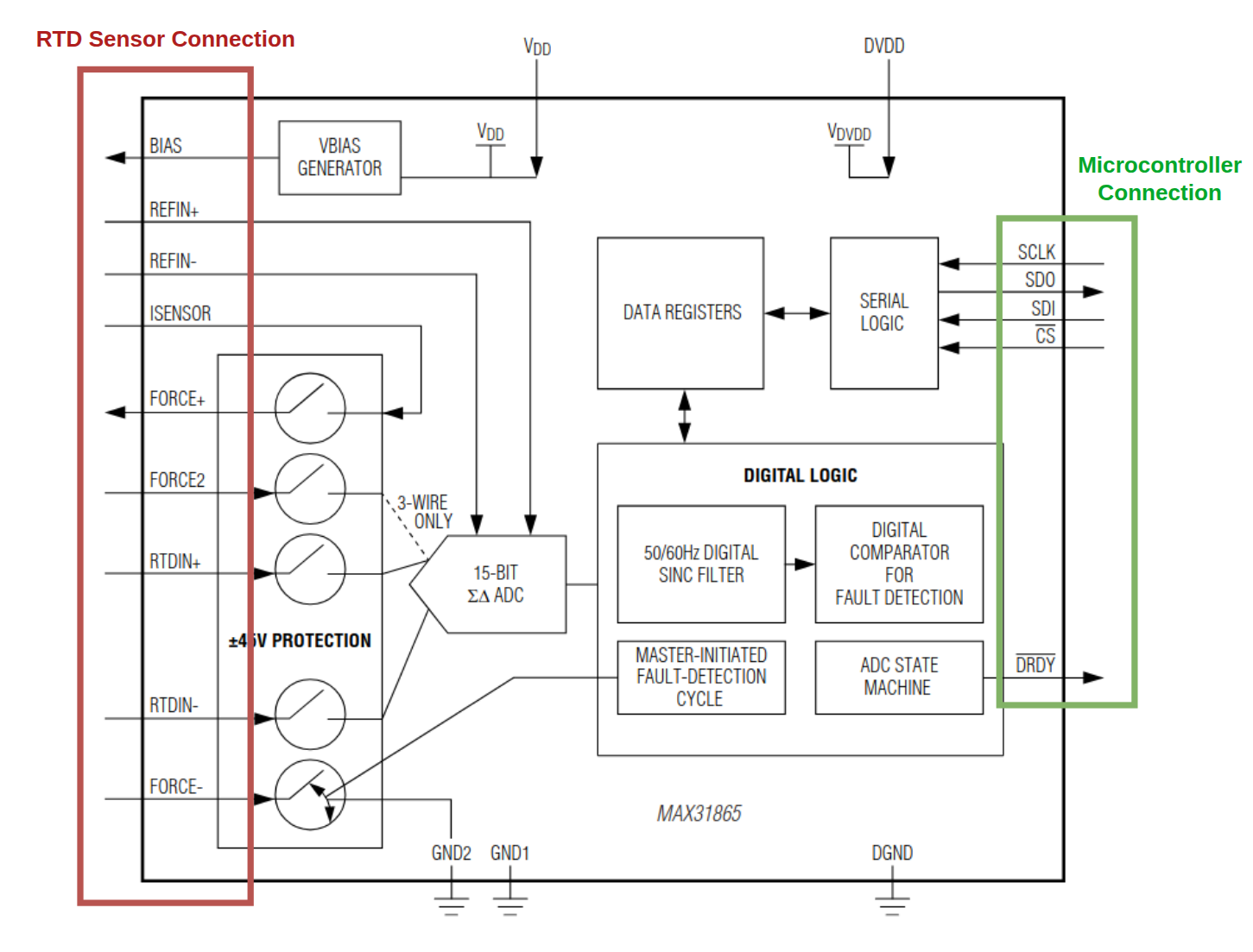
Due to the specialized circuitry needed to accurately measure the resistance across the RTD, there are a few integrated circuits on the market that automate reading them for us. One of these ICs is the MAX31865 RTD to Digital Converter.
This converter’s job is to continuously, or on command, measure the resistance across the RTD in 2, 3, or 4 wire mode and then store the resistance as a ratio between the RTD measured value and a reference resistor. This value is then stored in a register that can be read by a microcontroller over the SPI protocol. The microcontroller then converts that register value into a temperature in Celsius. You can see some of this in the block diagram for the MAX31865 IC from it’s datasheet:
Design & Manufacturing
There are breakout boards that are sold commercially that have this IC available to interface out of the box:
However, as this was a learning project at university, my team and I decided to design our own instead. We used KiCad for designing our PCB, and JLCPCB for manufacturing.
Requirements
First, we set some requirements for our PCB:
- Can be supplied by a 5V power supply (same as microcontroller in our design)
- Can attach 2, 3, or 4 wire RTD probes
- Compatible with 3V3 LVTTL logic, or TTL logic voltages.
- At least 1 or 2 mounting holes for securing the PCB
Because of these requirements, we chose the NCP1117-3.3 power supply, and a TXB0108PW level translator. This allows the board to talk to 5V or 3V3 logic level boards without the user having to worry about changing anything.
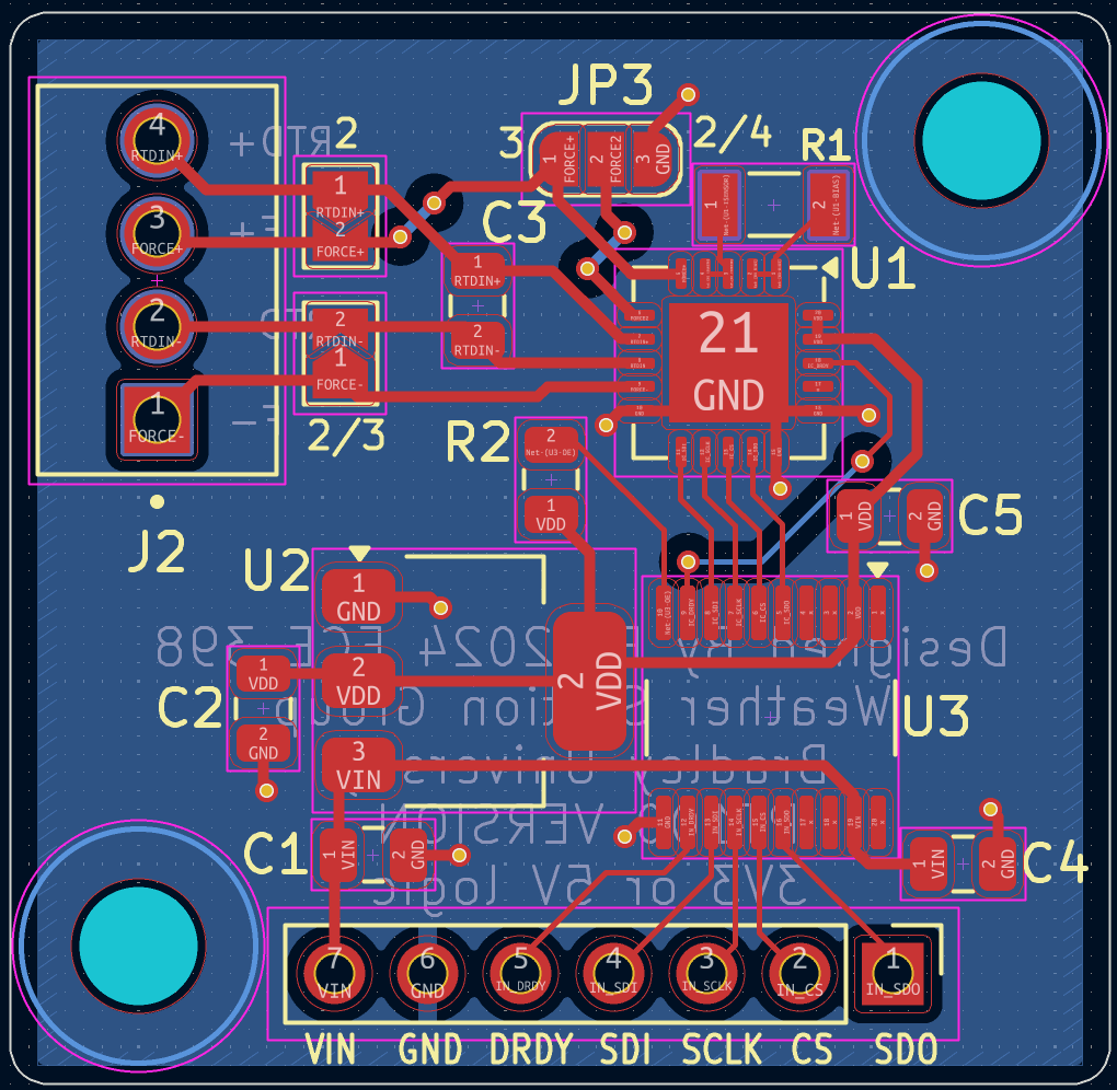
Electrical Design
We used the recommended design as per the datasheet, while also adding some solder jumpers that allow us to select between the 2, 3, or 4 wire types. They are located on the top of the PCB. The user simply solders/unsolders the jumper to select what sensor they are using:
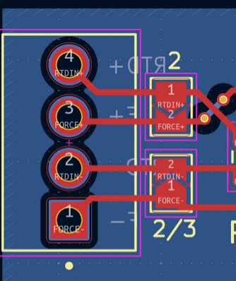
Other than that, there are screw terminals for connecting the sensor, and .1” pitch through-holes for connecting pin headers to the control and power signals that go back to the microcontroller.
Manufacturing
The PCB comes blank from JLCPCB with no components attached to it. Our team also purchased a stencil and solder paste to manufacture the boards. We used a custom reflow oven built out of a cheap toaster oven with a microcontroller and temperature sensor.
We made a jig for pasting the board, spread solder paste onto the contacts on the board, placed the components, and then placed the board into our custom reflow oven to run the temperature profile that solders the surface components to the board.
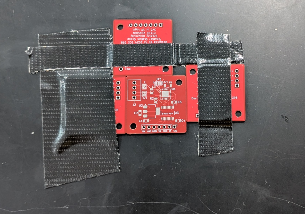
A jig made of other boards and duct tape for pasting the board
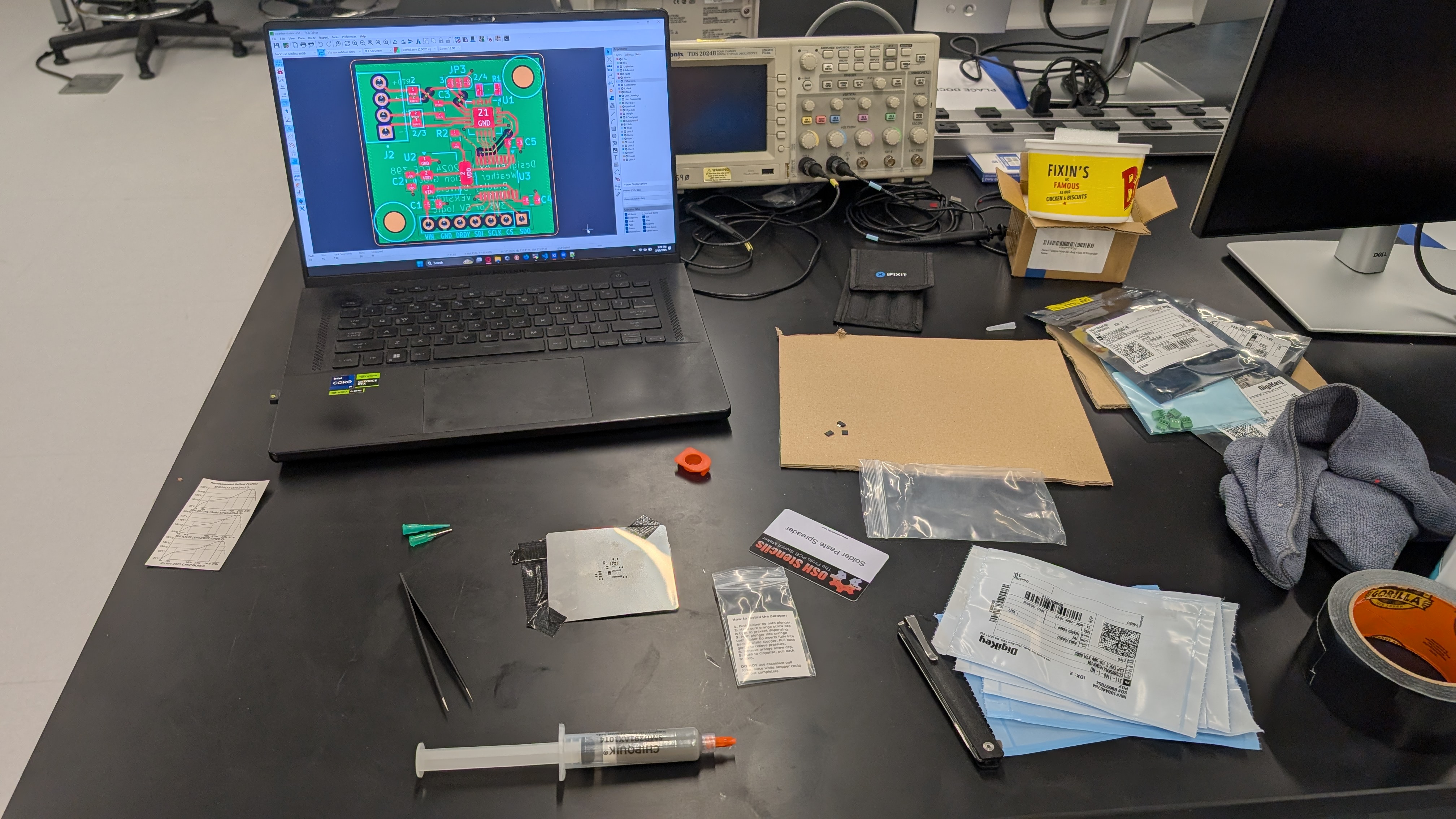
Pasting setup
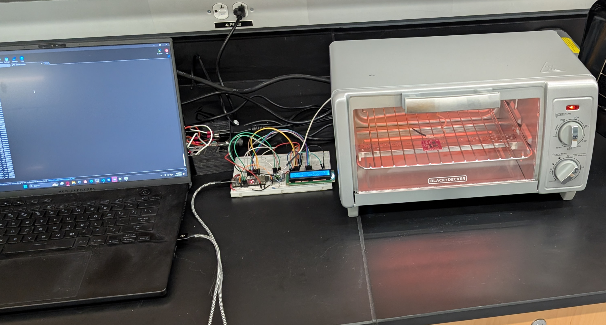
Reflowing the board in the custom-built oven
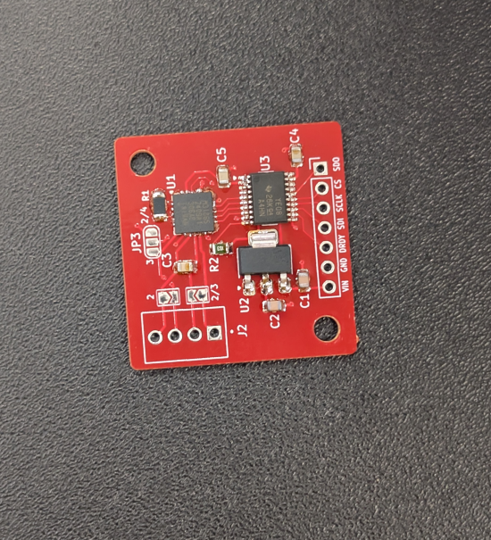
The board after reflow, which actually has some errors in the soldering. Some pins here are bridged.
Final Product
The final board was used in breadboards for development, and then finally put into a control board which is deployed in the weather station. Below is an image of the control board (which we also designed) and the control board deployed in the weather station outdoors.
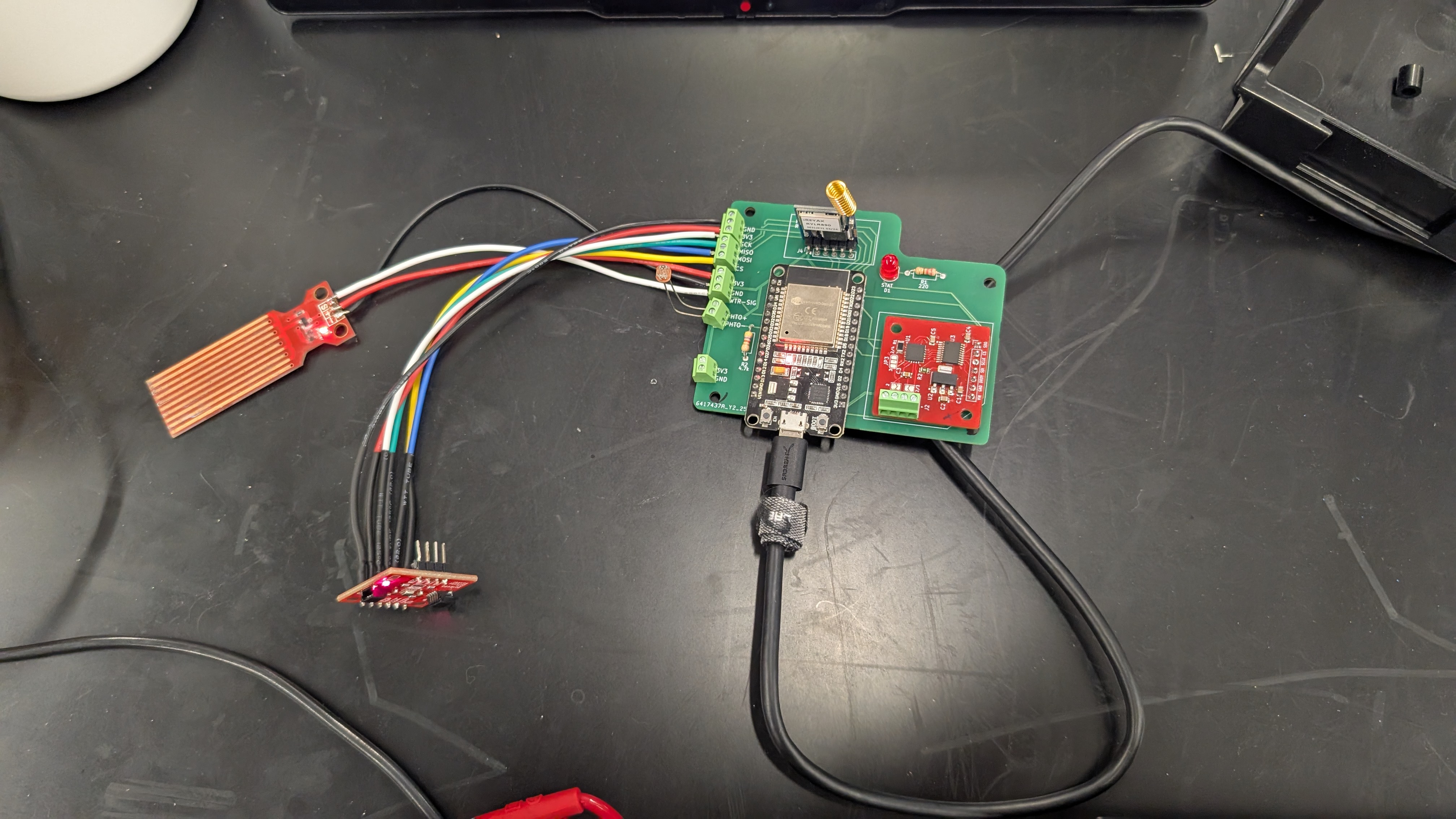
Control board with the custom RTD converter mounted on it
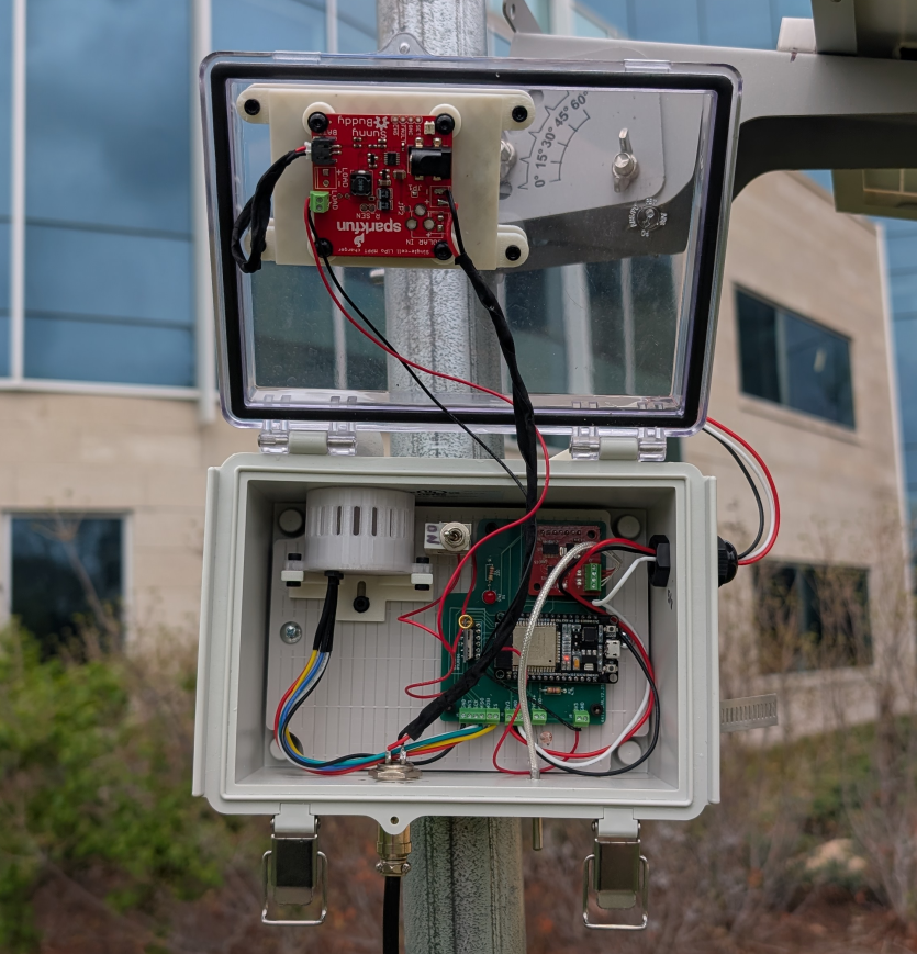
Control board mounted inside of the weather station outside (rtd board is the top-most component on the green board inside of the box)
Last Updated: 2025-08-16